Project Post: Robotic Arm
- Nate Hopper

- Jan 20, 2023
- 11 min read
Updated: Apr 3, 2023
Hello! Welcome to the comprehensive post for my Robotic Arm!
This post will detail the parts of the robotic arm, the code used to make it function, as well as other things I deem necessary to include within this post. Please note that this will be quite a long read, as this goes over every single part of the robot arm.
The Robot Arm
The Robotic Arm I am currently working on is a Scorbot ER-III Model Robotic Arm. The arm was manufactured by EShed Robotics. The Base has a 310 degree range of motion, the Shoulder and Elbow have a 130 degree range of motion, the Wrist Pitch has the same as Shoulder and Elbow, and the Wrist can roll a full 360 degrees.
All this info and more can be found in the Scorbot ER-III manual, linked here.
The arm also has a myriad of different components within it, which I will further detail in their respective sections. The components discussed will be the Motors, The Gripper, The Encoders, and The Microswitches.
The Motors
The motors are DC Servo Motors, which I can control directly using a MD17A DC Motor Driver. The motors are powered by 12 volts of electricity, which I have to carefully wire to make sure it does not interface with any other power busses on my boards.
The Gripper
The gripper is a claw that can be found at the top of the robot arm, and is possibly one of the most important parts of the arm. It is connected to two wrist joints, which gives it a large range of movement, including access to a 360 degree spin, allowing it to grab any item placed near it. The Gripper has padded ends for picking up items without causing harm to them, along with quite a large size range for items it can handle. The motors are also not strong enough to cause most objects to crush or break if it handles them.

The Encoders
While being a source of continued frustration for me, the encoders are extremely important to my goal in acquiring the full functionality of the robot arm for regular control. The Encoders are essentially the eyes of the robot arm, providing data on how much the arm has moved in any direction, along with knowing the direction it's going in.
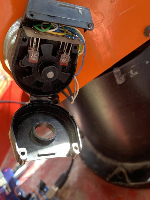
As one can see, there are 2 UV LEDs and 2 Photoreceivers (or are they photoresistors?) within the casing for the encoder. When the motor moves, the LEDs turn on, and the rotary in between the two spins. When the Photoreceivers 'see' the LEDs, they emit a pulse (I think) which can be read and used for measuring the amount of steps the arm takes.
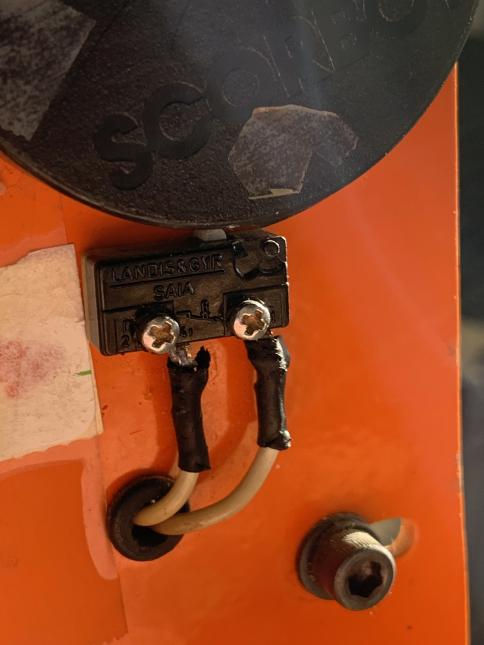
Microswitches
For my purposes, the microswitch essentially just exists to tell the arm when it's gone too far, or to set a point to move to until the switch is clicked. The point at which the arm clicks its switches can be altered by moving the arm and its motor caps by hand.
There's only 4 microswitches on the arm that I know of, one for the Base, one for the Shoulder, one for the Elbow, and only a singular one for the wrist. (Which I find weird because the wrist has 2 dedicated motors to enable a 360 degree spin for the arm.)
Non-Arm Hardware
The Non-Arm Hardware consists of technology I use to help program and control the robotic arm. Each piece of tech serves a function on the board, and contributes massively to the end goal of creating a working controller for the robot arm.
D50 Connector
The D50 connector (aka a D-SUB DB50 Female Header Breakout Board Terminal Block) is a 50 pin connector which is attached directly to a break out board which has 50 terminals that correlate directly to the pins in the D50 connector.
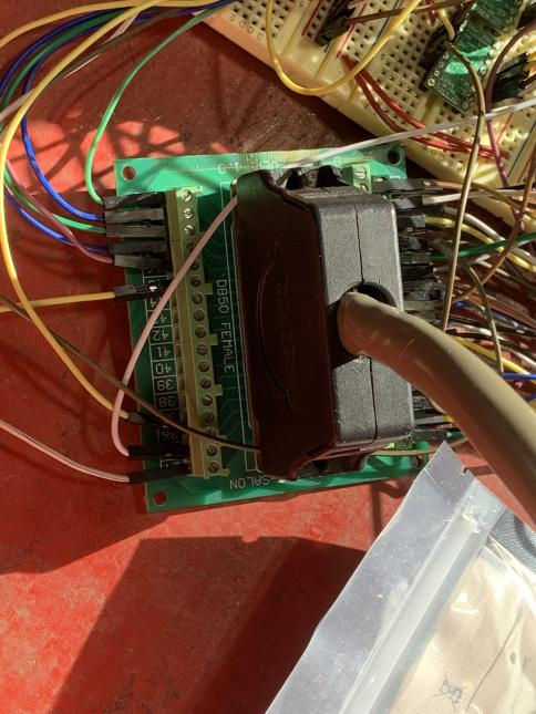
Before I acquired the D50 Connector, I was actually using a strange connector that had a D50 end, but wired into a 40 pin board that plugged into my breadboard. The board was very inefficient, lacking access to certain features, and having the grounds all tied together so I couldn't properly use microswitches and encoders at the same time.
The D50 connector has made my work substantially easier, and my only issue is that it doesn't really cut down on the wires I have, but that should be fixed when I have my circuit board completed for the arm.
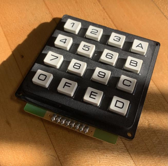
Keypad
The 4x4 Keypad is one of the two focal control methods for the robotic arm, possessing number keys corresponding to 0-9 and letter keys of A-F. Conveniently, the six letters allow me to use the letter keys for selecting the six motors in any control method. How that works will be explained more in the code segment of this post.
Joystick
The secondary control method of the robotic arm, the joystick is used for more free movement, and is easier to use than the keypad. It's the control method that was decided on for the average user, since it's fairly easy to understand and get to using with little to no instruction, even with the OLED Screen.


I pair its functionality with the keypad, using the keypad to be able to select what motor the joystick controls.
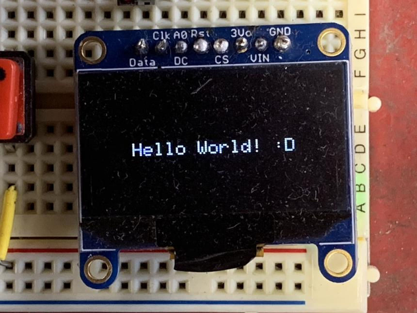
OLED Monitor
The OLED Monitor used in the project is a 128x64 OLED Monitor produced by Adafruit. It's a more recent addition to the project, being the only device that wasn't used in the era of the 40 pin board. Initially, the makeshift console for the robot arm was located entirely in Arduino's Serial Monitor, but it was decided that people should be able to see what the console says without having to plug into a computer, so I added the OLED Monitor. It's very handy to see exactly what motor is selected in joystick mode, along with displaying selection steps in keypad mode.
THE CODE
The following section will detail the program written to run the Robot Arm, along with the board used for programming. The plan is to have this section go as in depth as possible when overviewing my code, so please keep that in mind when reading.
The code is stored and executed from an ATMega2560, made by Arduino. The Board hosts 54 digital pins, 16 analog communication pins, 5 Ground Pins, a 3.3 Volt Output Pin, a 5 Volt Output Pin, and a Reset Pin. The board also possesses 4 Serial Pins, 6 Interrupt Capable Pins, and Data and Clock Communication.
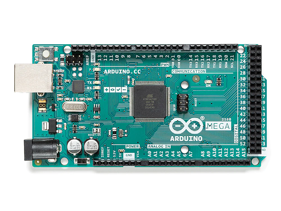
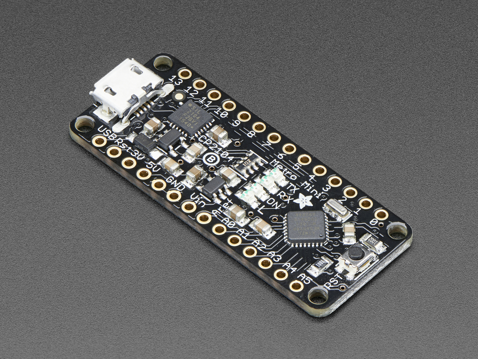
Initially, the code was run by an Adafruit Metro Mini, which has only 14 digital pins, 6 Analog Pins, along with having less Serial Communication, and only 2 Interrupt Pins. Early on in the creation process of a controller, the Metro Mini was deemed insufficient for the task, and was shelved in favor of the ATMega seen above, due to the ATMegas vastly larger amount of pins and functions.
This section will be updated occasionally as I make new breakthroughs in the code, and will often use the most recent version of my code.
If you would like to attempt to comprehend this code without my guide, the GitHub link is right here. (Please not my code is largely uncommented, an issue I need to fix.) If not, the explanation is beneath this line.
Passive Code:
Starting off with the bones of the code, we're going to take a look at all the code that sets up for the part of the program that interacts the most with the arm and components on the boards.
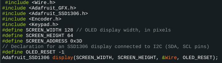
The first 10 lines of code are inclusions of libraries used to make the code run, notably the Keypad Library for Arduino by Mark Stanley and Alexander Brevig, the Encoder Library from PJRC, and the Adafruit Monochrome OLED Breakouts Library. These 10 lines also include establishing variables for the OLED Monitor, and a setup code for said Monitor.
Following these inclusions, then the code defines a total of 12 variables. Ten of the twelve variables are used exclusively by the keypad in its code section. The first 7 are selection states, which will be explained more in the keypad code section. The last 3 are sub selections within the VALUE selection state.
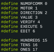
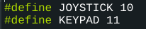
The last two variables are used to swap between control methods when needed, and are called on by two buttons on the board, which are individually labeled.
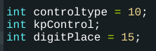
After this, we get to the changing variables. The first 3 following the defined variables are the switch state variables, two of which are set to default states, except for keypad control.
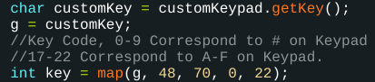
Next are the two single letter variables, g and s. s is a variable that will be seen a lot later, so I'll explain it when I get to it, but g is a variable I'll explain right now, since it has limited use in the code.

The g variable is used solely to map the char variables created from the keypad into easy to remember numbers for use in the code. There is a gap between the number keys and letter keys which I don't understand, but luckily the key variable works as intended in the code where it appears, so I'm not complaining.
Along with g, there are several other variables and setup code lines for the keypad, setting up the array for the keypad and allowing the keypad to be called on in the code.
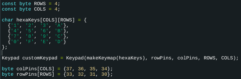
There are also the value arrays, which factored heavily into shortening the code into the length it currently is, and these arrays store values that get selected during the selection process.

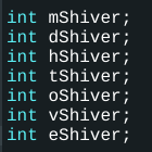
The value arrays also work very closely with the 'shiver variables,' which are 7 variables that are used when running through the keypad section of the code, and I'll go more in depth into what they're used for when we reach the keypad section.
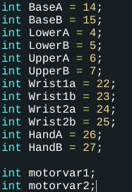
Following the arrays and their variables, we have the motor variables and their variables. The A and B variables are used later in the setup code when we declare the pins on the ATMega that get used to directly output to the motor drivers.
The motorvars get a lot more use when the joystick is the main control method, however at the end of the keypad code, the motorvars are crucial to making it all work. The motorvars were actually more efficient to use than outright calling on the individual motors everytime they were needed, so I heavily relied on them to help shorten the code.
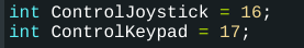
There are also the Control Swap variables, which are used to declare the pins that are used to read the buttons that swap between control schemes.
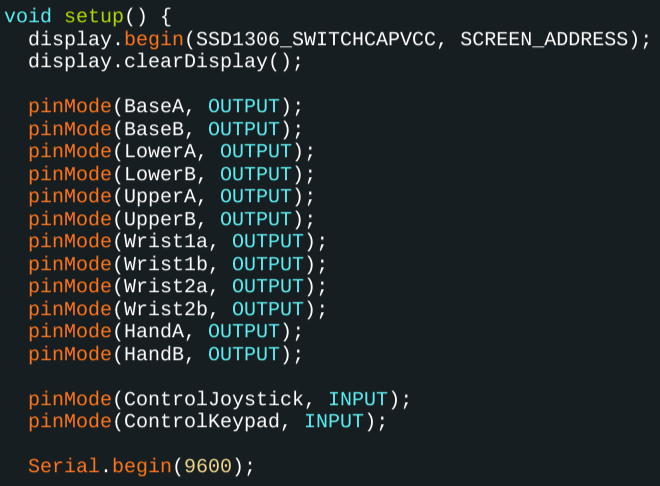
Finally breaking into the setup code, we have 2 lines for starting up the OLED Monitor, and then setting pins for the motors and control buttons, and a startup for the Serial Monitor, which remains for two reasons. Firstly, it's a remnant from old builds which focused on the Serial Monitor instead of the OLED Monitor, but secondly I keep it in case I need to make sure a variable or section of code is working properly.
Active Code:
Now, we get into the actual meat and potatoes of the code. This is, as the name implies, active code which means that compared compared to the setup code which is fairly static and only changes in specific situations, this code tends to be in use a lot more often, and interacts with the robot arm and the board components more often.
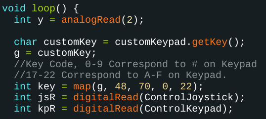
However before we get to any of the directly exciting code, we have a bit more set up. The y variable is a variable that will get used later, and I'll discuss it more when it pops back up. Then, after the previously explained keypad variable mapping, we have the joystick and keypad button readers, which constantly monitor the buttons used for input.
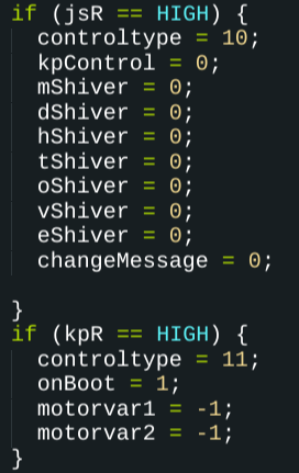
When an input is detected, the buttons will swap control types, while also acting as a sort of pseudo-reset button.
Swapping between control methods will reset all the main/important variables of that section's code, and can be used in a pinch in the keypad section if you don't feel like waiting to grapple with the edit function at the end of the section.
Resetting the joystick code isn't as important, but it makes it so that an unintended motor can't be moved before the user selects the motor.
This is a fairly important section of code, due to it actually being the foundation of swapping between the states of control, so it's good to give it some focus here.
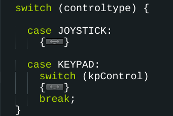
Finally, we get to the biggest section of the code. The section which has the most work put into it, and is a whopping 424 lines of code in it, is quite possibly my favorite part, due to how much I've worked on it, and due to how much shorter it is than the previous iteration which was over 1700 lines long.
We've come a long way.
Active Code - Subsection A: Joystick
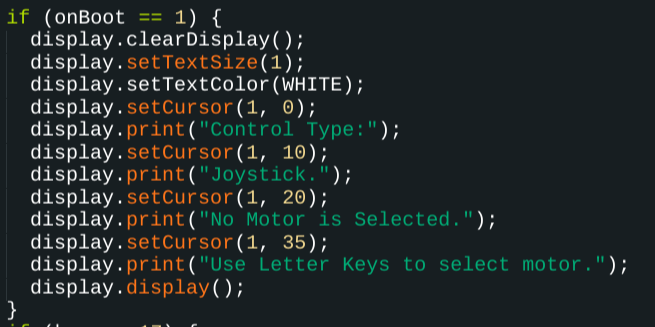
To start, we have the boot message. I call it that since it's the first thing to display on the screen whenever the code is powered on. The point of most of the OLED code is to tell the user of the arm what's going on at any given time, and point them in the right direction on how to use the arm.
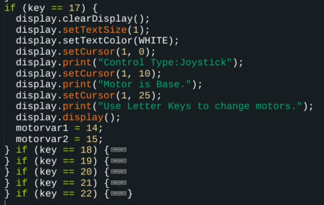
The joystick selection, which is primarily done through the keypad, works by simply swapping around the values of the motorvars. Along with this, it also changes the displayed motor on the OLED Monitor, so users can know what motor is active.
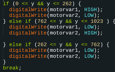
Finally at the end of the joystick section is the code for the joystick itself, which is only about 10 lines. The joystick, as previously explained, is essentially 2 potentiometers taped together with a small top on them, and thus using an analog pin, you can monitor one direction just like a potentiometer. Checking if the value is between a certain range on the potentiometer allows me to move the arm with the joystick.
Active Code - Subsection B: Keypad
After the simplicity of the joystick, the keypad will definitely seem more complex, but it's actually quite simple.
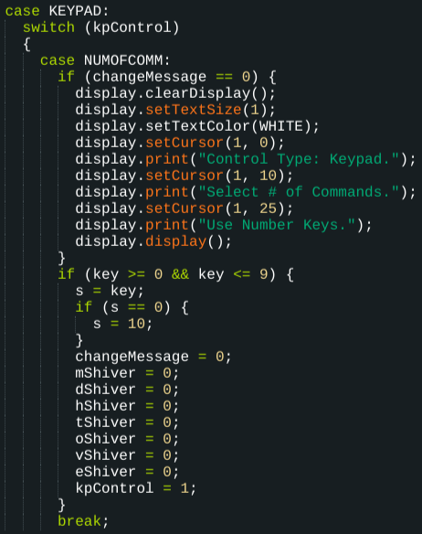
Starting off is the selection command for the number of commands. This will determine how a lot of the code works.
Remember the s variable? Alright well, we're gonna take a look at it now. By pressing a number key during this state, this will register a value from 1-10 to the s variable. Due to the lack of a 10 key, the 0 key will store a 0 value, which if detected, will be set to 10 instead of 0.
After the s variable is set and stored, the code resets the shiver values, along with changeMessage (in which NUMOFCOMM is the only command that uses it) and moves onto motor selection.

For the next 5 states, the code is going to look very similar to one another. It follows the structure of
Displaying the current information on the selection state, along with informing how many selections the user needs to make
Using the shiver variables to count through the selections, along with using them to store variables in each slot of the array.
Moving onto the next selection state after all selections have been made.
There are a few sections that are slightly different though, which I'll go over.
The direction selection section is a unique case, only having two possible inputs, being one or zero. The display does clarify which direction is which (1 is reverse, 0 is forward) so users know that there are only two options.

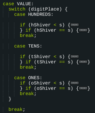
After that is the VALUE case, which is notable for having 3 selection states within it, being for each place in the 3 digit numbers used for the execution phase of the code.
Value is also the only case not to have an OLED monitor code directly in it, due to it conflicting with the OLED code in the Hundreds, Tens, and Ones sections.
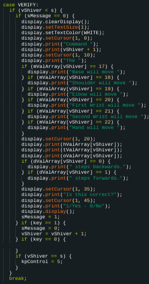
The penultimate section of code, the verification sequence isn't as complicated as it may look on the surface.
The code starts by printing out your entire command on the OLED Monitor, starting with the Motor , then steps and direction. It will then ask you if the input is correct. Selecting yes will repeat the process until all commands have been verified.
Selecting no takes you to the edit function. While not yet complete, I can outline the direct function of the edit function. The edit function takes the vShiver value and prints out the aspects of the command, and will allow you to directly edit the part you're unhappy with, be it direction, motor, or step value.
Once you've finished editing and verifying all your comments, the code will move onto the execution portion of the code.
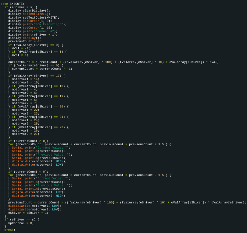
The execute section holds the distinction of having the longest single line of code in the entire program. It might also be the longest overall section of code as well. Before execution, the program quickly does some math, storing a value of 0 as the current value, then adding the amount of steps to the current value, while also checking if the dVal is equal to 0 or 1, and multiplying them by -1 or 1 respectively. Then, the code will set the motor values using the saved value in the mValArray. Taking all these into account, the code will then execute one of two for loops, based on whether or not the step value is positive or negative. It will then move the motors until a certain value is exceeded, set the motors to low, wipe the current value, and repeat until all commands are complete.
The keypad section will then repeat itself as many times as the user needs. This concludes the keypad section dissection!
Conclusion
This is an excessively complicated set of code, and is only going to get longer. I plan on adding more functions to the code to improve the user experience. Eventually I also hope to make a full fledged controller, which will also be shown off in this blog post. I will regularly update this post when notable improvements to my code happen! Please stay tuned, and thank you so much for reading!
Comments